up: Chapter 2 -- Basic Programming Model
prev: 2.2 Data Types
next: 2.4 Instruction Format


2.3 Registers

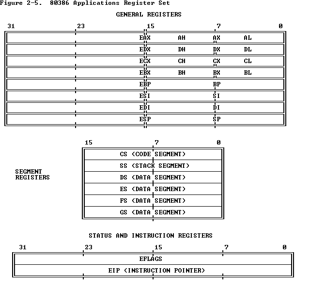
The 80386 contains a total of sixteen registers that are of interest to the applications programmer. As Figure 2-5 shows, these registers may be grouped into these basic categories:
  1. General registers. These eight 32-bit general-purpose registers are used primarily to contain operands for arithmetic and logical operations.
  2. Segment registers. These special-purpose registers permit systems software designers to choose either a flat or segmented model of memory organization. These six registers determine, at any given time, which segments of memory are currently addressable.
  3. Status and instruction registers. These special-purpose registers are used to record and alter certain aspects of the 80386 processor state.

2.3.1 General Registers

The general registers of the 80386 are the 32-bit registers EAX, EBX, ECX, EDX, EBP, ESP, ESI, and EDI. These registers are used interchangeably to contain the operands of logical and arithmetic operations. They may also be used interchangeably for operands of address computations (except that ESP cannot be used as an index operand).

As Figure 2-5 shows, the low-order word of each of these eight registers has a separate name and can be treated as a unit. This feature is useful for handling 16-bit data items and for compatibility with the 8086 and 80286 processors. The word registers are named AX, BX, CX, DX, BP, SP, SI, and DI.

Figure 2-5 also illustrates that each byte of the 16-bit registers AX, BX, CX, and DX has a separate name and can be treated as a unit. This feature is useful for handling characters and other 8-bit data items. The byte registers are named AH, BH, CH, and DH (high bytes); and AL, BL, CL, and DL (low bytes).

All of the general-purpose registers are available for addressing calculations and for the results of most arithmetic and logical calculations; however, a few functions are dedicated to certain registers. By implicitly choosing registers for these functions, the 80386 architecture can encode instructions more compactly. The instructions that use specific registers include: double-precision multiply and divide, I/O, string instructions, translate, loop, variable shift and rotate, and stack operations.

2.3.2 Segment Registers

The segment registers of the 80386 give systems software designers the flexibility to choose among various models of memory organization. Implementation of memory models is the subject of Part II -- Systems Programming. Designers may choose a model in which applications programs do not need to modify segment registers, in which case applications programmers may skip this section.

Complete programs generally consist of many different modules, each consisting of instructions and data. However, at any given time during program execution, only a small subset of a program's modules are actually in use. The 80386 architecture takes advantage of this by providing mechanisms to support direct access to the instructions and data of the current module's environment, with access to additional segments on demand.

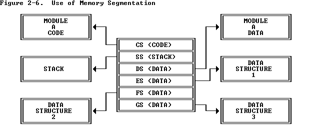
At any given instant, six segments of memory may be immediately accessible to an executing 80386 program. The segment registers CS, DS, SS, ES, FS, and GS are used to identify these six current segments. Each of these registers specifies a particular kind of segment, as characterized by the associated mnemonics ("code," "data," or "stack") shown in Figure 2-6 . Each register uniquely determines one particular segment, from among the segments that make up the program, that is to be immediately accessible at highest speed.

The segment containing the currently executing sequence of instructions is known as the current code segment; it is specified by means of the CS register. The 80386 fetches all instructions from this code segment, using as an offset the contents of the instruction pointer. CS is changed implicitly as the result of intersegment control-transfer instructions (for example, CALL and JMP), interrupts, and exceptions.

Subroutine calls, parameters, and procedure activation records usually require that a region of memory be allocated for a stack. All stack operations use the SS register to locate the stack. Unlike CS, the SS register can be loaded explicitly, thereby permitting programmers to define stacks dynamically.

The DS, ES, FS, and GS registers allow the specification of four data segments, each addressable by the currently executing program. Accessibility to four separate data areas helps programs efficiently access different types of data structures; for example, one data segment register can point to the data structures of the current module, another to the exported data of a higher-level module, another to a dynamically created data structure, and another to data shared with another task. An operand within a data segment is addressed by specifying its offset either directly in an instruction or indirectly via general registers.

Depending on the structure of data (e.g., the way data is parceled into one or more segments), a program may require access to more than four data segments. To access additional segments, the DS, ES, FS, and GS registers can be changed under program control during the course of a program's execution. This simply requires that the program execute an instruction to load the appropriate segment register prior to executing instructions that access the data.

The processor associates a base address with each segment selected by a segment register. To address an element within a segment, a 32-bit offset is added to the segment's base address. Once a segment is selected (by loading the segment selector into a segment register), a data manipulation instruction only needs to specify the offset. Simple rules define which segment register is used to form an address when only an offset is specified.


2.3.3 Stack Implementation

Stack operations are facilitated by three registers:
  1. The stack segment (SS) register. Stacks are implemented in memory. A system may have a number of stacks that is limited only by the maximum number of segments. A stack may be up to 4 gigabytes long, the maximum length of a segment. One stack is directly addressable at a -- one located by SS. This is the current stack, often referred to simply as "the" stack. SS is used automatically by the processor for all stack operations.
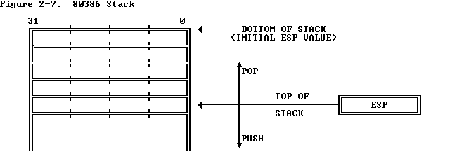
  2. The stack pointer (ESP) register. ESP points to the top of the push-down stack (TOS). It is referenced implicitly by PUSH and POP operations, subroutine calls and returns, and interrupt operations. When an item is pushed onto the stack (see Figure 2-7 ), the processor decrements ESP, then writes the item at the new TOS. When an item is popped off the stack, the processor copies it from TOS, then increments ESP. In other words, the stack grows down in memory toward lesser addresses.
  3. The stack-frame base pointer (EBP) register. The EBP is the best choice of register for accessing data structures, variables and dynamically allocated work space within the stack. EBP is often used to access elements on the stack relative to a fixed point on the stack rather than relative to the current TOS. It typically identifies the base address of the current stack frame established for the current procedure. When EBP is used as the base register in an offset calculation, the offset is calculated automatically in the current stack segment (i.e., the segment currently selected by SS). Because SS does not have to be explicitly specified, instruction encoding in such cases is more efficient. EBP can also be used to index into segments addressable via other segment registers.

2.3.4 Flags Register

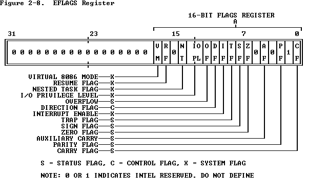
The flags register is a 32-bit register named EFLAGS. Figure 2-8 defines the bits within this register. The flags control certain operations and indicate the status of the 80386.

The low-order 16 bits of EFLAGS is named FLAGS and can be treated as a unit. This feature is useful when executing 8086 and 80286 code, because this part of EFLAGS is identical to the FLAGS register of the 8086 and the 80286.

The flags may be considered in three groups: the status flags, the control flags, and the systems flags. Discussion of the systems flags is delayed until Part II.

2.3.4.1 Status Flags

The status flags of the EFLAGS register allow the results of one instruction to influence later instructions. The arithmetic instructions use OF, SF, ZF, AF, PF, and CF. The SCAS (Scan String), CMPS (Compare String), and LOOP instructions use ZF to signal that their operations are complete. There are instructions to set, clear, and complement CF before execution of an arithmetic instruction. Refer to Appendix C for definition of each status flag.

2.3.4.2 Control Flag

The control flag DF of the EFLAGS register controls string instructions. DF (Direction Flag, bit 10) Setting DF causes string instructions to auto-decrement; that is, to process strings from high addresses to low addresses. Clearing DF causes string instructions to auto-increment, or to process strings from low addresses to high addresses.

2.3.4.3 Instruction Pointer

The instruction pointer register (EIP) contains the offset address, relative to the start of the current code segment, of the next sequential instruction to be executed. The instruction pointer is not directly visible to the programmer; it is controlled implicitly by control-transfer instructions, interrupts, and exceptions.

As Figure 2-9 shows, the low-order 16 bits of EIP is named IP and can be used by the processor as a unit. This feature is useful when executing instructions designed for the 8086 and 80286 processors.


up: Chapter 2 -- Basic Programming Model
prev: 2.2 Data Types
next: 2.4 Instruction Format